1 Working on our camera system
Our second-iteration Display Interposer has finally shipped from our PCB fab, and we're expecting to receive it tomorrow. Once we receive it we'll be able to ship it to our PCBA, and after that we'll be able to continue working on the final assembly of our review units.
In the meantime, we've been working on our front-facing camera system, which will provide the Simula One with its AR Mode:

AR mode is useful when you want to walk around, see the keys on your keyboard, or take a sip of your desk coffee :]
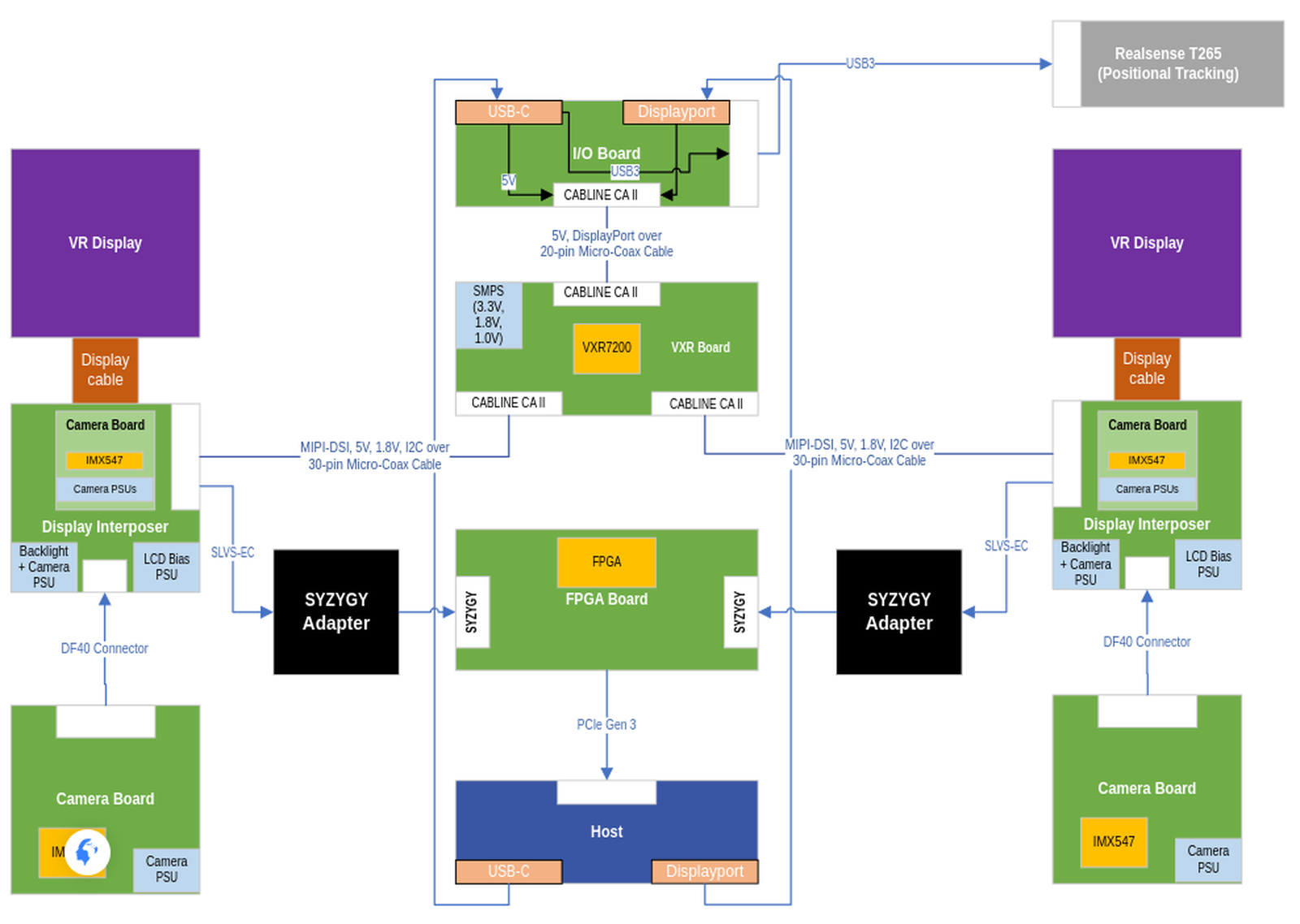
The thing we've been working on this last week is what we are calling a "Camera Syzygy Adapter", which is a board that connects our two cameras to our FPGA. Here's a high-level block diagram showing how it will fit in with everything else:
2 Dissecting our FPGA
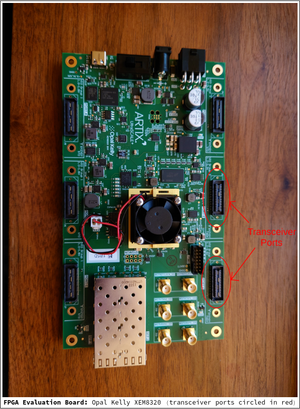
Zooming in a bit: our Simula One internal prototype is using an Opal Kelly XEM8320 evaluation board. The XEM8320 contains 6 external Syzygy ports ("Syzygy" being the name of the extension port interface and protocol), 4 of which are "standard ports" and 2 of which are "transceiver ports":
The following schematic shows a breakdown of how everything is being used:
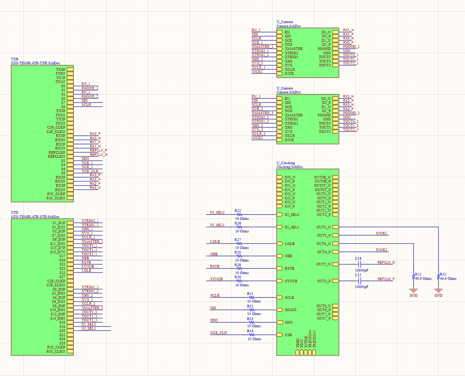
In our case, we plan to use 1 transceiver port + 1 standard port.
2.1 The Transceiver Port
The transceiver ports contain access to the high-speed lanes which we need in order to transmit our large amount of camera data. Roughly speaking: (i) we need ~5Gbps of bandwidth for camera transfer, (ii) a a typical FPGA I/O port can usually service 1.5-2.5Gbps, but (iii) the high-speeds lanes provided by this FPGA provide us with 16Gbps (far in excess of our requirement 👍).
Each transceiver port has 1 quad (4 RX & TX lanes, plus a reference clock) exposed, where RX stands for "receiver" and TX stands for "transmitter". In turn, each lane consists of a _P + _N pair (driven in opposite directions for signal integrity reasons):
![]()
Each of our camera boards (one for each eye) requires two transceiver (RX) lanes to transmit camera data through. As shown in the diagram, the TX pins will not be used.
The full transceiver port schematic can be found here.
2.2 Standard Port
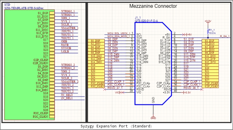
A single standard port will be used for other auxilliary camera functions (enable, reset, vsync/hsync, configuration stuff, etc).