1 Towards AR Mode
The Simula One will feature two front-facing RGB cameras for its AR Mode:
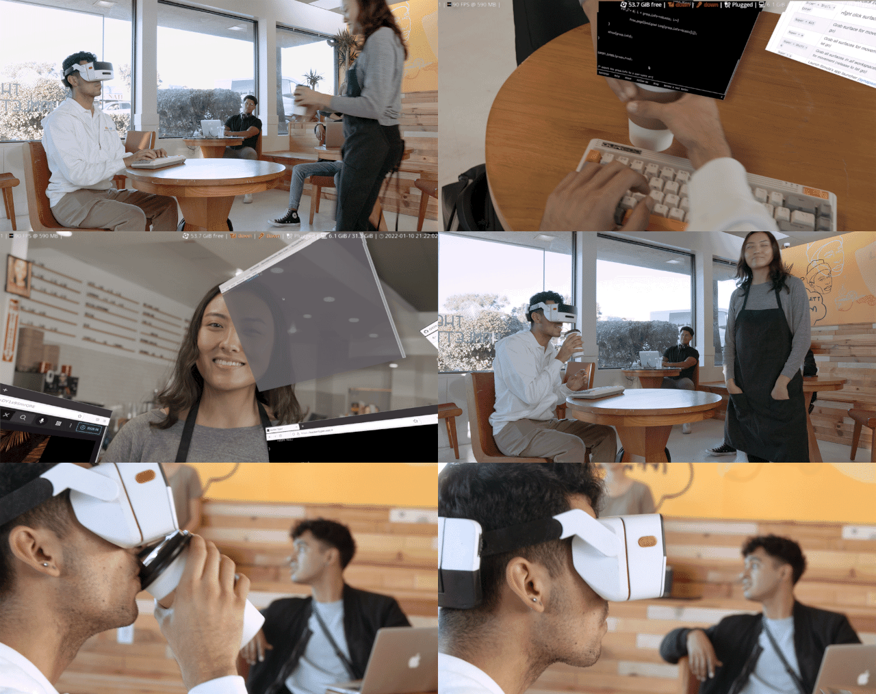
This is useful for things like
- Viewing keyboard keys
- Seeing coworkers
- Navigating while walk-computing
- Grabbing (and yes, sipping :) your cup of coffee while wearing your VRC
2 Why two cameras are required instead of one
First off: why are two cameras required instead of one? Wouldn't one front-facing camera be simpler and save on bandwidth and cost? The answer is due to parallax:
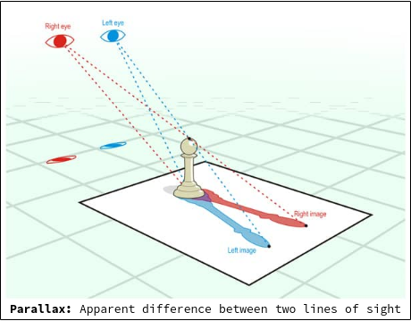
Parallax is the difference in the apparent position of an object viewed along two different lines of sight. If your brain doesn't see parallax simulated in VR, it gets seriously disoriented.
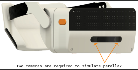
This is why when an image of a scene is rendered inside your headset, there are actually two slightly different images displayed for each eye: the right-eye image is offset slightly to the right, while the left image is offset slightly to the left. When it comes to simulating AR Mode with front-facing cameras, the parallax requirement doesn't change! This is why two cameras must be attached to the front of the headset: one for each eye, slightly offset from one another.
3 Camera requirements
We have not made a selection of our actual camera module yet, but our requirements are roughly:
| Spec | Requirement | Notes |
|---|---|---|
| Resolution: | ≥ 2,000 x 2000 | Ideally camera resolution matches our display resolution (2,448 x 2,448), modulo performance & bandwidth issues |
| Image Capture Speed: | 90 fps | Camera capture speed should match our target compositor FPS |
| FOV: | 100° | Camera FOV should match our VR FOV |
| Minimum Object Distance: | ~20cm | 20cm is adequate for, e.g., looking at keyboard keys while typing |
| Sensor Size: | ~1/1.8" | |
| Shutter: | Global | We're willing to experiment w/rolling shutters to cut down on costs |
3.1 Comparing our camera specs to other VR headsets
Since VR computing is our exclusive focus, and VR computing requires a good AR mode, we are pushing a bit harder on our camera specs than some other VR headsets.
| Headset | Resolution | Camera Type |
|---|---|---|
| Simula One | ≥ 2,000 x 2,000 | RGB |
| Valve Index | 960x960 | RGB |
| Oculus Quest 2 | 640x480 | Monochrome |
Many other VR headsets (e.g. the Varjo Aero) don't even come with cameras.
3.2 Global versus rolling shutters
In our spec table we mention we prefer "global shutters". The distinction between a global and rolling image sensor is in how it grabs image data.
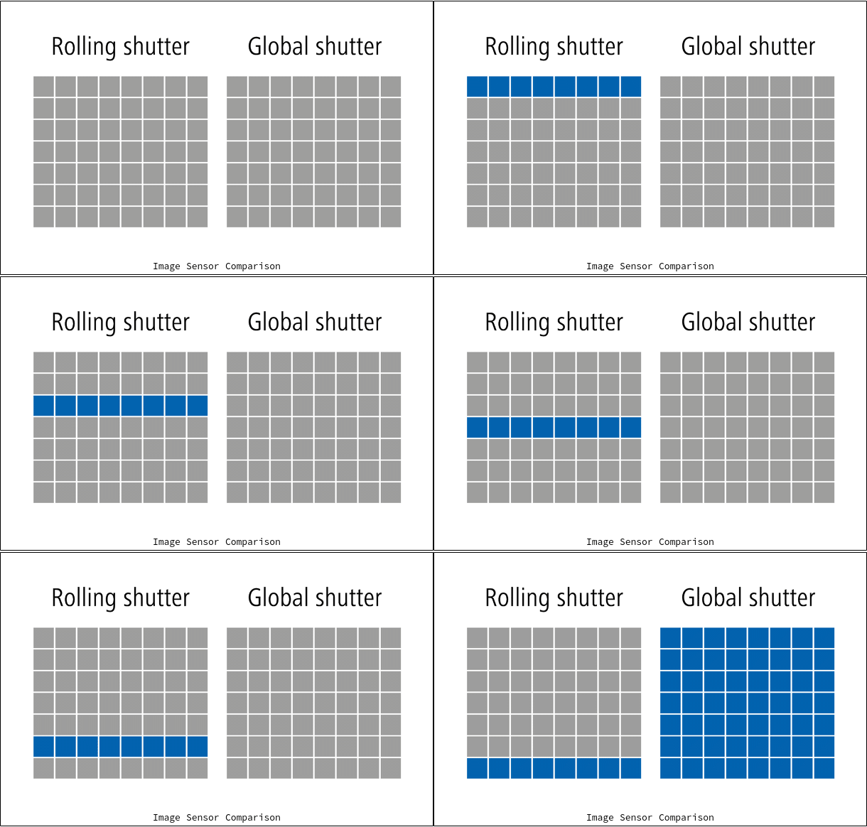
- Rolling shutter. Each frame of image data is captured by scanning across the scene, typically one row at a time (causing artifacts).
- Global shutter. Each frame of image data is captured across the entire image sensor at once.
For our purposes, global shuttering offers the following advantages: less AR Mode motion artifacts, better image quality, and easier to use with computer vision. With that said, global shuttering is more expensive, since more chip space is required to store the extra sensor pixels each frame. While we prefer global shuttering from the outset, our plan is to evaluate both types of sensors for AR Mode image quality.
4 Image sensors under consideration
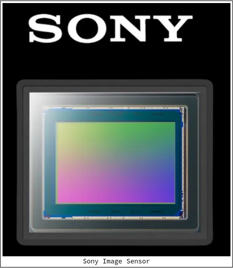
Our two image sensors under consideration are both Sony image sensors, differing primarily in their shutter type:
| Model Name | Shutter Type | Pixels | Resolution | Sensor Size | Frame Rate |
|---|---|---|---|---|---|
| Sony IMX547 | Global Shutter | 5.1 MP | 2472 x 2064 | 1/1.8" | 122 FPS |
| Sony IMX715 | Rolling Shutter | 8.29 MP | 3840 x 2160 | 1/2.8" | 90.9 FPS |
At this point we prefer the Sony IMX547, since it has the global shutter type.
4.1 Next steps: evaluating the the IMX547 for optical performance
Our next steps for camera evaluation involve two phases:
-
Phase 1: Evaluate cameras with an evaluation board for optical performance. Here we will just plug the IMX547 camera sensor into a stock evaluation board (provided by Sony under NDA), connect it to our Intel NUC (aka the Simula One's computer), and evaluate it for good image quality.
-
Phase 2: Evaluate the cameras with our custom assembly for headset performance. Even if our camera is suitable when tested on an evaluation board, this doesn't necessarily mean it will work well in our actual headset assembly. Towards this end, David has been working on a sensor module for the Sony IMX547 (shown below), which will be a part of a system to test bandwidth, latency performance, and AR passthrough quality in our actual headset.
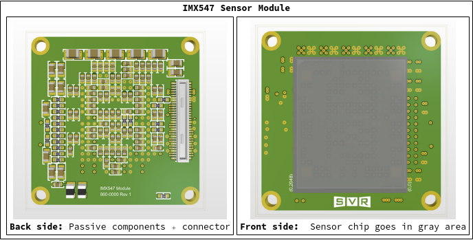
Using this sensor module, the data flow inside our headset will look roughly as follows:
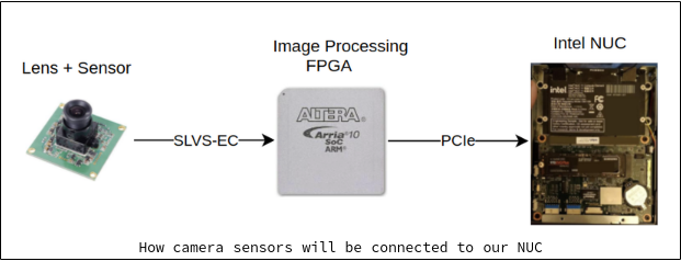
In this system, light passes through the lens and into our image sensor, which is then passed into our image processing FPGA (via the "SLVS-EC" protocol) for demosaicing. Afterwards the processed image data is passed via PCI Express to our NUC, where our VR compositor will finally be able to process the image and show it in the appropriate eye when AR Mode is activated.
In this data flow, our primary bandwidth bottleneck is the PCIe connection between the FPGA and the NUC. Here we are using a PCIe x4 (Gen 3) connection, which can pass data at a speed of 35.5 Gb/sec.
4.2 More on our FPGA's "demosaicing"
We mentioned above that image data is passed from our image sensor to our FPGA for "demosaicing". What exactly does this mean?
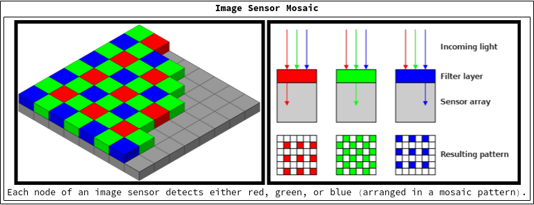
Under the hood, an image sensor (like the Sony IMX547) contains a grid of non-overlapping Red, Green, and Blue photosensors. As light hits the sensor, each of these photosensors only detects its corresponding color (red, green, or blue). This means the image sensor lacks complete color data in every node, which necessitates further image processing (in our FPGA) to interpolate the missing color details.
As an example, the following (non-overlapping) photosensor nodes are split up into red, green, and blue photosensor nodes:
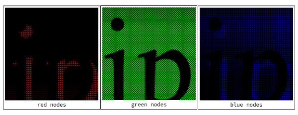
As can be seen above, an (e.g.) "red" node in the sensor lacks "green" and "blue" data. To fill in for the missing color data, a process called "demosaicing" has to be undertaken, which interpolates the unknown color data for each node.
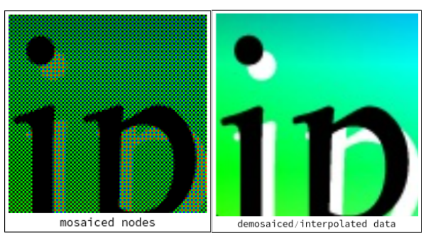
The end result is a recognizable image with full color data in every pixel.
5 Latency issues
The final issue to discuss is camera latency. According to an early VR article by John Carmack:
Human sensory systems can detect very small relative delays in parts of the visual or, especially, audio fields, but when absolute delays are below approximately 20 milliseconds they are generally imperceptible.
A total system latency of 50 milliseconds will feel responsive, but still subtly lagging.
Thus a good camera latency target for our camera system is ≤20ms, while a less ambitious (but still reasonable) latency target would be ≤50ms.
5.1 Estimating our latency to be ≤20ms
We won't actually know what our camera latency will be until we test our assembly, but a rough calculation shows that we're at least in the running for a ≤20ms camera latency:

The assumptions we make to get here are pretty in the weeds, but if you're interested, here they are:
- We allocate
1ms(rounded up) for light to hit our image sensor. - We compute it takes
4.22msto transfer a frame of image data from our camera to our image processing FPGA.- The number of pixels being pushed per frame from the camera to the FPGA is
2448x2048(as per our sensor documentation). - Each pixel contains
1 byteof color data. - Thus
2448 * 2048 * 1 byte = 5.014MB ≈ 5MBof data is sent from the camera sensor to the FPGA each frame. - Our camera sensor sends data through
2lanes at a speed of4.752 Gbpsper lane, or9.504 Gbpstotal (as per the SLVS-EC spec). - Thus
5.014MB/t = 9.504 Gbps ⇒ t = 4.22ms
- The number of pixels being pushed per frame from the camera to the FPGA is
- We compute it takes
3.81msto transfer a frame of data from the FPGA to our NUC.- Since there are now 3 bytes of data per pixel (Red byte + Green byte + Blue byte) due to FPGA demosaicing, we must now send
2448 * 2048 * 3 bytes = 15.042MB ≈ 15MBof color data per frame to the host. - Gen 3 x4 PCIe throughput is
31.5 Gbps(according to Wikipedia). - Thus
15MB/t = 31.5 Gbps ⇒ t = 3.81ms
- Since there are now 3 bytes of data per pixel (Red byte + Green byte + Blue byte) due to FPGA demosaicing, we must now send
- We assume it takes at most
1ms(from the point the FPGA starts to receive image sensor data) for the FPGA to start sending processed image data to the host. - After a frame is fully processed and prepared by the host, we assume it takes
~5msfor the frame to transfer to the display.
Conclusion: Rounding everything up to the nearest millisecond, we can put these together into a coarse latency calculation which implies an AR Mode camera latency of ~15ms.